Constructive Solutions for the Stabilization of a Major Landslide

Following the presentation delivered at the IX National Symposium on Slopes and Unstable Hillsides, held in Santander in 2017, we published in Ingeopres magazine a summary of the solution designed by Orbis Terrarum, for which we also carried out construction supervision.
This major landslide occurred in 2015 at PK 437+200 of the N-I road, destroying a service station, following multiple previous smaller slides.
The solution consisted of a combination of soil nailing, drainage trenches, IRS anchors, and a pile wall.
This combined design ensures long-term stability through structural reinforcement and drainage control.
After the successful publication of this summary in the press, we now invite you to consult the extended version of the article as presented at the IX National Symposium on Slopes and Unstable Hillsides.
STABILIZATION TECHNIQUES FOLLOWING THE REACTIVATION OF A LARGE LANDSLIDE IN TOLOSA (GIPUZKOA).
Fernando PUELL*, Javier MARÍN†
Dr. Civil Engineer (Roads, Canals, and Ports), Orbis Terrarum.
Civil Engineer, MSc in Geological Engineering, Orbis Terrarum.
RESUME
The landslide described in this communication is located on the N-I road, specifically at kilometer point (KP) 437.200, on the right-hand side of the road (in the direction of San Sebastián), within the municipality of Tolosa (Gipuzkoa). In February 2015, a major landslide occurred, destroying a service station. This event followed several landslide episodes in previous years. The stages followed during the construction of the main stabilization elements—primarily soil-nailing, drainage trenches, IRS anchors, and a pile wall—are described. Additionally, key aspects managed by Orbis Terrarum during the execution phase of the project are detailed.
INTRODUCTION
This document presents the construction solutions and execution measures proposed by Orbis Terrarum for the stabilization of a major landslide located at KP 437 + 200 of the N-I road in the direction of San Sebastián, in the municipality of Tolosa (Gipuzkoa), as well as the technical constraints encountered during the project's execution.
The aforementioned landslide occurred in February 2015, with disastrous consequences for the service station located at the foot of the slope, which was completely buried. The affected hillside had undergone slope modifications to facilitate the construction of the aforementioned service station in 1994, altering the natural slope from approximately 18–20° to a 34° slope (3H:2V) with a height between 3 and 5 meters, which was reinforced with a gabion wall. Although technical details are limited, the initial landslide occurred in the same year the service station was built, causing the collapse of 15 to 20 meters of the gabion wall. These were subsequently repaired by replacing the clayey material in the wall's backfill with gravel and installing riprap counterforts.
In February 2013, further movements occurred, deforming the wall and impacting the service station's ground, causing heaving and the formation of a large tension crack at the crown of the landslide. These movements were addressed through a construction project that involved the creation of a berm of variable height and a 50–60° slope, complemented by concrete-filled riprap at the backfill of the gabion wall, while installing instrumentation systems to monitor the slope's movements.
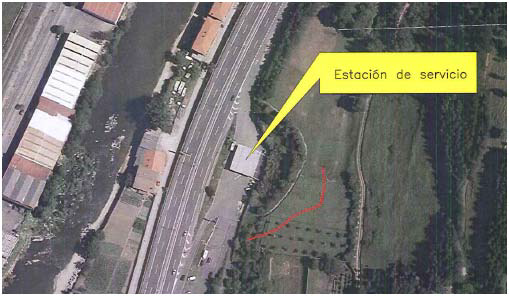
Fig. 1: Aerial view of the study area in April 2013, showing the location of the landslide tension crack.
Finally, in February 2015, after recording anomalies in the monitoring systems following a period of heavy rainfall, and without sufficient time to implement remedial measures, a failure occurred, which ended up burying the service station building. An emergency intervention was carried out, involving the removal of soil from the upper part of the slope to temporarily mitigate the retrogressive effect of the landslide.
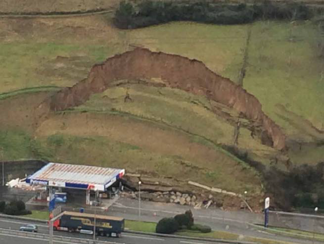
Fig. 2: Landslide of February 2015.
Following the completion of various investigations, in February 2016, Orbis Terrarum was commissioned to prepare a report on stabilization measures, which subsequently...
...led to the development of the detailed design and the site supervision of the projected works, which were successfully executed between June and October 2016.
GEOLOGICAL AND GEOTECHNICAL DESCRIPTION
The hillside in question corresponds to the left bank of the Oria River as it passes through the town of Tolosa, in the province of Gipuzkoa. The landslide is located adjacent to the small embankment that forms the N-I road at this location.
Geologically, the slope consists of a natural soil cover formed by colluvial deposits of variable thickness, composed of firm-consistency brown clay with significant gravel content and traces of sand. These soils overlie the clayey materials of the Keuper Triassic.
El Keuper está constituido por arcillas versicolores con cantidades muy variables de gravas y arena de consistencia firme a muy firme, siendo posible observar la presencia de yesos blanquecinos y ofitas muy alteradas.
In addition to the aforementioned materials, which are in contact with the Keuper Triassic via a fault, calcareous materials are present, consisting of dolomitic limestones, calcareous breccias, and rauhwackes. These materials can be found both as very sound strata and as alternations with zones of voids and gravel-like textures.
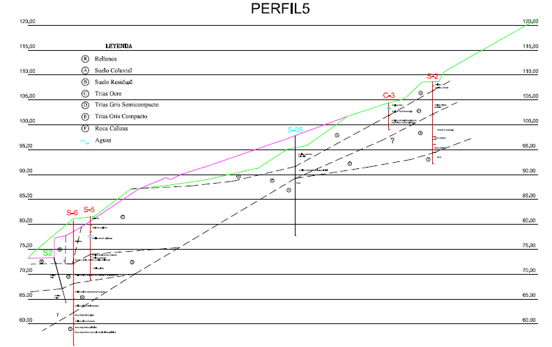
Fig. 3: Interpreted geotechnical profile, January 2016.
DESIGN OF STABILIZATION MEASURES
Based on the available data from previous geological and geotechnical studies, a back-analysis was carried out by modeling the morphology and hydrogeological conditions of the slope prior to the landslide. This allowed for the verification of the parameters assigned in said studies, as well as the groundwater level, for their use in the design of the remedial measures.
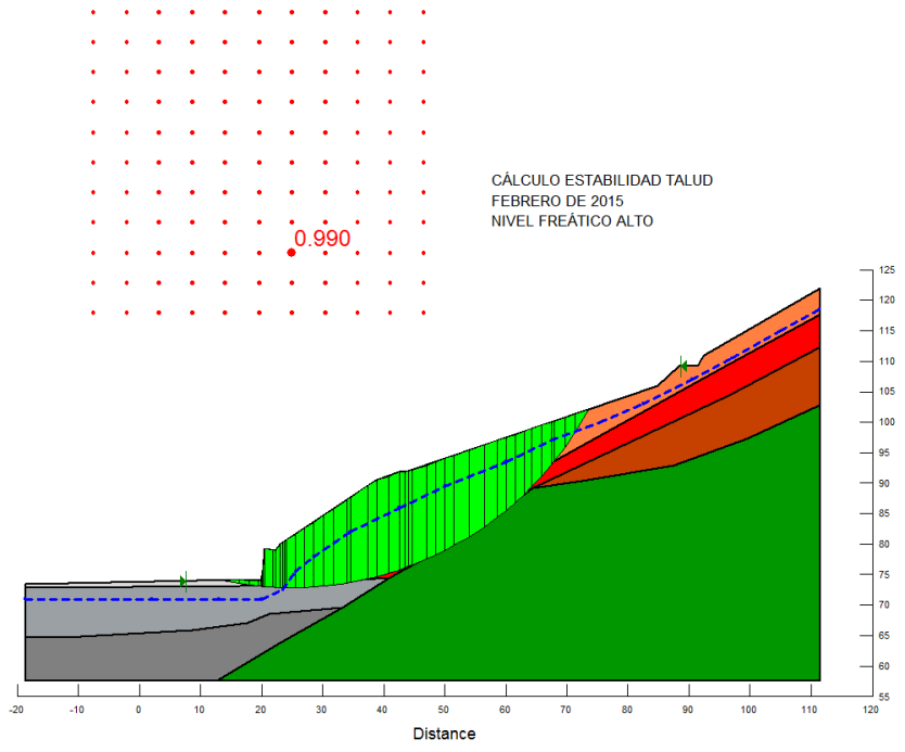
Fig. 4: Back-analysis with high groundwater level hypothesis, February 2015. FS=0.990.
The designed intervention had to be comprehensive in nature, acting upon the entire sliding mass to stabilize it. Likewise, it was essential to guarantee the stability of the retaining structures, which would allow for the reconstruction of the service station and prevent the retrogressive action of the landslide further up the slope.
With the aforementioned objectives in mind, several measures were designed to stabilize the landslide, which are summarized below:
- Soil nailing At the head of the landslide, in order to increase safety during the remaining operations and prevent the retrogressive action of the slide, a soil-nailing intervention was designed using staggered nails in a 3×3 m grid, with lengths ranging from 4 to 5 meters.
- Excavation and slope reshaping (o regrading) In the intermediate zone of the landslide, slope reshaping was performed, establishing a maximum slope of 22-23°, with the objective of removing material from the upper and middle zones. This reduced the total earth pressure on the retaining structures and provided a more stable slope.
- Concrete wall and cable anchors (o Ground anchors) As a primary stabilization measure, 8-strand active anchors with Repetitive and Selective Grouting (IRS) were designed, with a total length of 29 m. These were installed on a concrete wall, inclined at 60° to the horizontal, which acts simultaneously as both a retaining element and a distribution beam.
- Drainage trenches (o French drains) 3 meters deep, designed to control surface water and prevent uplift pressure acting on the retaining structures.
- Piled wall (o Secant/Tangent pile wall) Due to space constraints for the reconstruction of the service station building, a pile wall was designed as the final retaining measure at the front of the landslide, allowing for a completely vertical alignment in the required position. The wall consists of 130 cm diameter piles spaced at 145 cm center-to-center, with a total length of 12.20 m, 4 meters of which act as a cantilever. These are tied together by a capping beam. Furthermore, the cantilevered face of the pile wall was shotcreted, and sub-horizontal drains (California drains) were installed between the piles to ensure that no water is retained behind the wall (trasdos).
- Muro de escollera y cierres de escollera Regarding the slopes, the lateral closures of the pile wall and the remaining slopes were designed using more flexible solutions (riprap walls and facing), thus avoiding the cost increase that would have resulted from fully closing the entire slope with the aforementioned structural solutions.
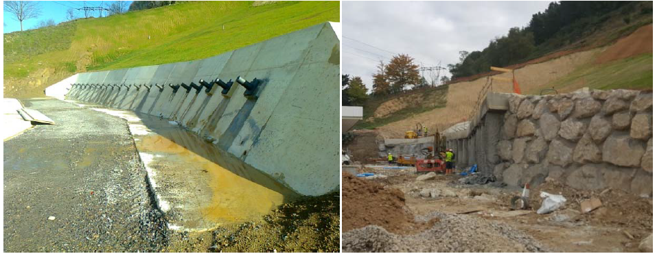
Fig. 5: Views of the completed anchored wall (left) and the riprap wall and pile wall (right).
CONSTRUCTION EXECUTION AND QUALITY CONTROL
To ensure that construction works were carried out under safe conditions, the project required the implementation of strict construction phases, where each phase could not commence until the previous one had been completed. The projected phases were as follows:
- Phase 1: Execution of soil-nailing at the head of the landslide slope.
- Phase 2: Excavation and regrading of the upper slope down to the design elevation at a 37° gradient. Execution of the lower soil-nailing section.
- Phase 3: General slope reshaping of the intermediate zone at a 23° angle. Excavation of the drainage trenches.
- Phase 4: Construction of the anchored wall by the "hit-and-miss" method (or "by panels"). General excavation. Execution of the pile wall.
- Phase 5: Excavation down to the service station elevation, shotcreting of the pile wall, and installation of sub-horizontal drains (California drains).
- Phase 6: Construction of the riprap wall at the southern end of the slope. Creation of the maintenance access road. Revegetation of the intervention area and final site cleanup.
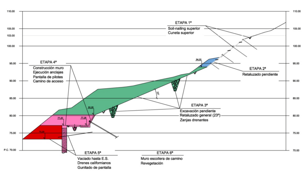
Fig. 1: Sketch of the construction phasing for the proposed measures.
The execution of the aforementioned measures was carried out under the supervision of the Site Management (consisting of Orbis Terrarum technical staff), based on three lines of action aimed at ensuring the correct performance of the designed measures:
- Material Control A reception control process was implemented for all materials supplied to the site, as well as for those manufactured on-site or specifically for the project (concrete, steel, grout, etc.).
- Topographic Control From the start of the works, topographic monitoring benchmarks were established, allowing for weekly auscultation of slope movements. Furthermore, these benchmarks and the procedures developed during construction have served as the basis for the current periodic monitoring program.
- Control de Ejecución: Continuous monitoring of the construction works was implemented to ensure that the designed measures were executed correctly, allowing for necessary adjustments to the original designs. Furthermore, integrity testing of piles and investigative and remedial testing of anchors were performed.
Regarding civil works, it is worth highlighting the expertise acquired in designing anchor testing protocols, which enable in-situ performance verification and the optimization of the designed bond lengths. Due to the project's tight schedule, investigation testing had to be conducted prior to the construction of the concrete wall, which was designed to act as a waler beam and load distribution surface.
Conducting investigation tests involves applying loads significantly higher than the design loads directly onto the natural ground. This necessitates a robust design of load distribution elements to prevent exceeding the ultimate bearing capacity and causing a surface failure. This constraint required the construction of large, temporary concrete blocks to serve as distribution elements for the correct performance of the tests.
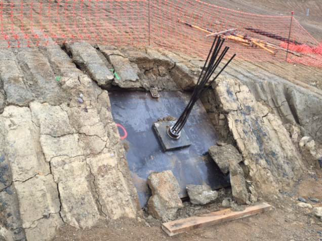
Fig. 2: Rotura del terreno en superficie.
CONCLUSIONS
Faced with various solutions proposed by different ground treatment contractors, the project developer opted to commission an engineering project to integrate the available data, thereby optimizing the solution from an engineering perspective with a long-term focus.
The experience gained from the project under discussion highlights the importance of a deep understanding of the mechanisms involved in this type of landslide, which is essential for a correct analysis of the triggering factors and a robust design of the stabilization measures.
Furthermore, the complexity of the site's geology and the designed measures necessitates the presence of on-site technical specialists. This allows for real-time decision-making in response to unforeseen conditions or difficulties encountered during execution, ensuring that any necessary adjustments do not compromise the fundamental design concepts of the project.
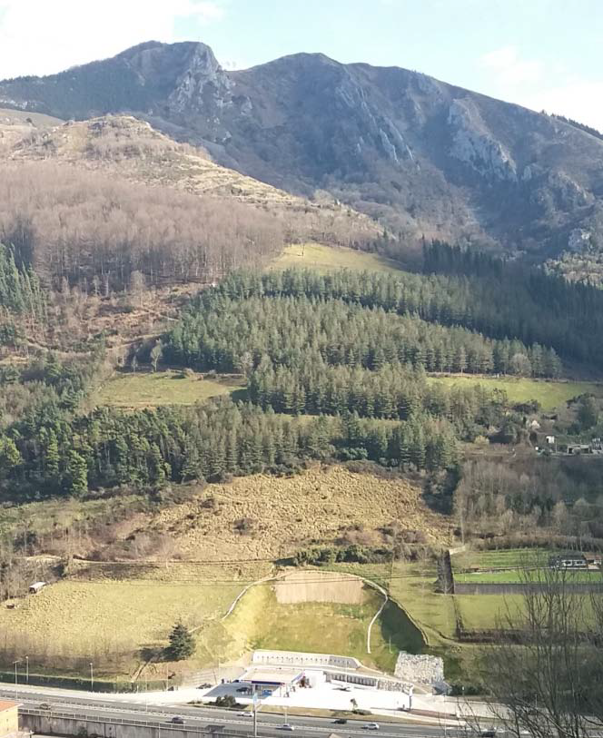
Fig. 3: General view of the completed project.

