Update of the Technical Specifications for Geotechnical Studies in Photovoltaic Plants 2024
After investigating more than 620 solar plants in different countries around the world, completing over 50 GW studied, we are pleased to announce the update of our Technical Specifications for Geotechnical Studies in Photovoltaic Solar Plants. This document presents the most currently requested tests for geotechnical design and corrosion protection. It also provides revised recommendations for the design of geological and geotechnical investigation campaigns for new photovoltaic solar plants.
TECHNICAL SPECIFICATIONS FOR PROCUREMENT OF GEOLOGICAL AND GEOTECHNICAL STUDIES IN SOLAR PV PLANTS
Authors: Fernando Puell Marín1, José Alberto López Chinarro2
1 PhD in Civil, Structural, and Hydraulic Engineering
2 Geotechnical Engineer & EuroGeologist (EurGeol) ORBIS TERRARUM
Key Words: Solar PV Plants / Photovoltaic Power Plants, Renewable Energy / Green Utilities, Geotechnical Engineering / Ground Engineering, Laboratory Testing, In-situ Testing / On-site Testing, Electrical Resistivity Tomography (ERT), Soil Corrosivity / Corrosion Analysis, Expansive Clays / Shrink-swell Soils.
Resume: Photovoltaic power plants are facilities that typically span large land areas. Consequently, geological and geotechnical conditions can vary significantly within the same site. For this reason, a proper geotechnical campaign design is essential to mitigate geological uncertainties. This article provides key recommendations based on Orbis’s extensive experience conducting geotechnical studies for solar PV plants across numerous countries (see world map in www.orbisterrarum.es ).
1 INTRODUCTION
This document provides key recommendations for designing an appropriate geological and geotechnical site investigation campaign for new solar photovoltaic plants (PV plants). These recommendations are based on ORBIS TERRARUM’s extensive track record, having investigated more than 620 solar power plants across various countries worldwide, representing over 50 GW of installed capacity.
Cost and timeline optimization is inherently integrated into the proposed investigations. A comprehensive geological and geotechnical study is always essential to accompany any solar photovoltaic power plant project, providing valid design data while mitigating long-term risks and operational issues. Furthermore, the formal and administrative requirements stemming from guarantees during financing, asset acquisition, or divestment processes must not be overlooked.
Among the aspects that the geotechnical study must undoubtedly address, the following can be highlighted:
- Zoning the different terrain types based on geology and defining the boundaries of unsuitable areas for module installation.
- Determining the feasibility of driven piling for solar module foundations.
- Analyzing the soil corrosion potential for structural steel and concrete elements.
- Providing electrical resistivity data for the design of the grounding network.
- Providing soil mechanics parameters, such as shear strength and ground deformability, to be used in foundation design.
- Evaluating ground excavability and recommending the appropriate excavation machinery.
- Recommending safe slope inclinations to ensure stability during excavations.
- Providing allowable bearing capacities for shallow foundations.
- Evaluating the capacity of deep foundations, to be subsequently verified through pull-out testing, which will also provide ground deformability data.
- Detecting geological and ground-related hazards, such as seismic activity, soil collapsibility, flood risk, highly erodible areas, pre-existing slope landslides, and karst terrain.
- Detecting geological and ground-related hazards, such as seismic activity, soil collapsibility, flood risk, highly erodible areas, pre-existing slope landslides, and karst terrain.
- Detecting the groundwater table level and defining the primary hydrogeological aspects.
- Determining the thermal resistivity of the natural ground at varying moisture content levels.
The following sections analyze the site investigations, laboratory testing, and report contents, providing a bill of quantities (BoQ) to serve as a preliminary reference for PV plant developers and sponsors when requesting a quote for a geotechnical study.
Where applicable, these studies must be supplemented by specific assessments for transmission lines, electrical substations, or project access roads, all of which are generally subject to local regulations.
2 SITE INVESTIGATIONS
2.1 Geological Mapping
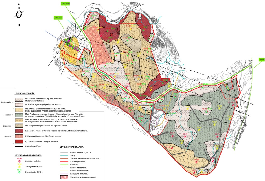
A surface geological mapping survey will be required. This mapping is generally based on direct field observations (geotechnical investigations, regional geological materials, outcrops, and geomorphology), literature reviews, and the interpretation of indirect geophysical testing results, such as electrical resistivity tomography (ERT). At rock outcrops, rock mass ratings (RMR) / geomechanical stations will be conducted to assess the weathering degree, fracturing, and overall structure of the rock mass.
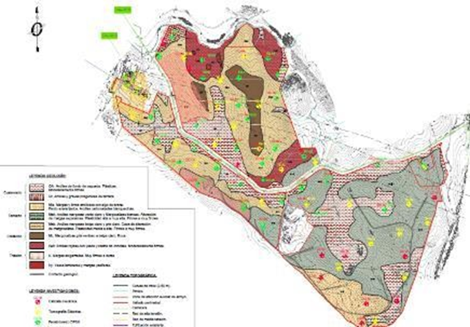
Fig. 1: Detailed Geological Mapping by ORBIS TERRARUM
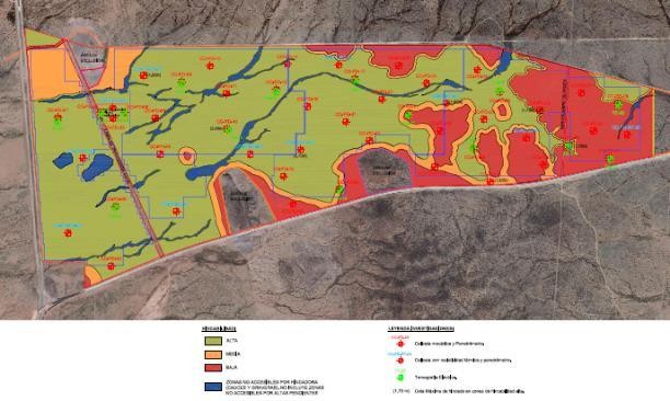
Fig. 2: Detailed ramming feasibility plan by ORBIS TERRARUM
2.2 Test Pits
Direct investigations are typically carried out using mechanical test pits up to a depth of 3.5 m, thereby exceeding the embedment depth of the future metallic posts that support the PV panels. Furthermore, these investigations are useful for characterizing the ground beneath other facilities (such as inverters or lightweight buildings) for the geotechnical design of foundations. During excavation, a specialized technician (geologist or geotechnical engineer) will log a geological-geotechnical description of the soil strata and collect representative samples (soil, rock, and water). Any noteworthy features, such as the presence of artificial fills or evidence of contamination, will be documented. Upon completion, each test pit will be backfilled with the excavated material and properly compacted to prevent any hazard to people or livestock.
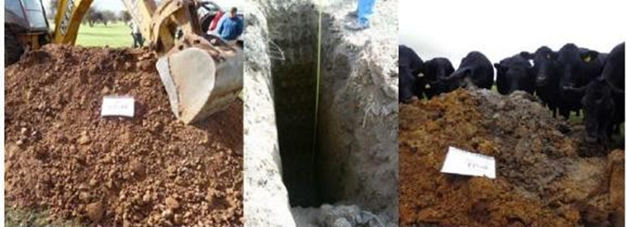
Fig. 3: Mechanical trial pit for subsurface investigation and sample collection.
Although not always required, test pits may be supplemented with geotechnical boreholes with core recovery, infiltration or permeability testing, and seismic refraction or passive seismic surveys (ReMi) for sites with high seismic risk. Ground Penetrating Radar (GPR) may also be employed; specifically, Orbis’s geophysics department utilizes GPR for the detection of archaeological remains and buried utilities.
Prior to the commencement of the geotechnical campaign, it is necessary to identify any potential existing buried services to establish the exact location for the investigations.
2.3 Dynamic Penetration Testing
Dynamic probing is the most suitable method for estimating ground resistance, assessing the piling feasibility of steel profiles, and achieving precise site zoning due to its ease of use, portability, and cost-effectiveness compared to other techniques. The use of light dynamic penetrometers, such as the Panda2, is common, particularly in soft soils and areas with difficult access. Heavier penetrometers, such as the DPSH (Dynamic Probing Super Heavy) type, are routinely used in stiffer or harder ground. Results from both test types can be correlated with SPT (Standard Penetration Test) values.
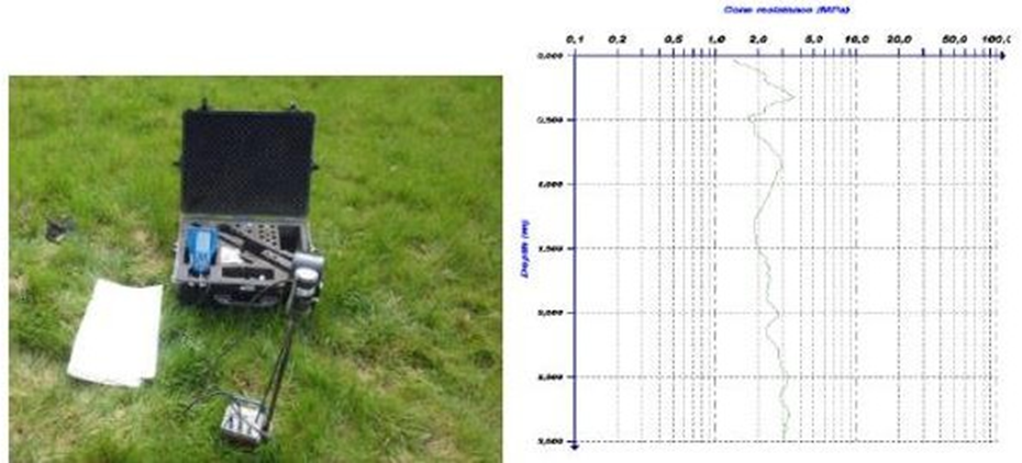
Fig. 4: Panda2 dynamic penetrometer and resulting penetration log.
Con los equipos de penetración dinámica se puede estimar la resistencia de las diferentes unidades geológicas observadas en las calicatas.
In regions where these penetrometers are not widely used, they may be replaced by continuous SPT (Standard Penetration Test) sampling performed up to the required depth (typically 3.0 m to 4.0 m).
Regarding the above, it is critical to determine the thickness of the topsoil layer. This surface layer generally exhibits low bearing capacity and variable organic matter content. As this soil is rarely stripped—especially on flat, level sites—it is recommended to exclude its thickness and resistance from the design calculations for the pile embedment length.
2.4 Electrical Resistivity
The most common and comprehensive investigation method is Electrical Resistivity Tomography (ERT) using a Wenner array configuration with 21 or 42 equidistant electrodes along a line. This configuration allows for the determination of the ground's electrical resistivity both horizontally along the survey line and with depth. The interpretation of these results enables a representation of the various geological units within a longitudinal profile.
Alternatively, Vertical Electrical Soundings (VES) can be performed to determine electrical resistivity at a single point across varying depths. However, this technique has been largely superseded by Electrical Resistivity Tomography (ERT), as the latter offers the distinct advantage of providing a continuous geological interpretation over a significantly larger area
Determining electrical resistivity is of paramount importance for assessing the corrosivity potential of soils and is equally vital for the design of the grounding system.
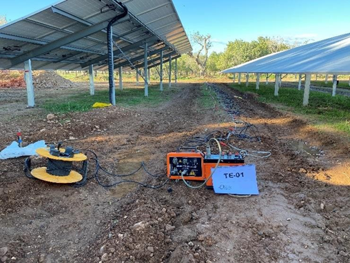
Fig. 1: Geophysical survey using Electrical Resistivity Tomography (ERT).
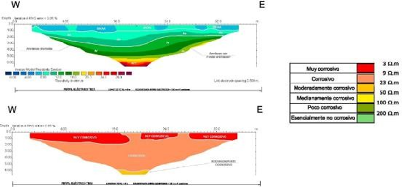
Fig. 5: Electrical Resistivity Tomography (ERT) profile interpretation: geological units and cathodic corrosivity potential assessment.
Electrical resistivity measurements can also be performed in the laboratory using the Soil-Box apparatus. In this method, measurements are conducted on compacted saturated samples.
followed by saturation with distilled water. This method is the recommended practice for classifying soil corrosivity potential according to U.S. standards.
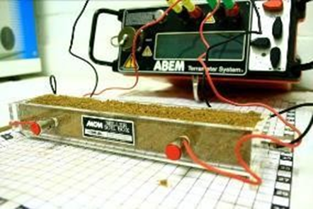
Fig. 2: Laboratory electrical resistivity measurement using a Soil-Box apparatus.
2.5 Thermal Resistivity
Soil thermal resistivity is a measure of the soil's ability to conduct or dissipate heat generated by a source (typically power or electrical cables). In the case of electrical trenches, it is essential to determine the thermal properties not only of the native soil but also of the backfill material.
Thermal resistivity tests are performed within open trenches or other excavations. This allows for in-situ measurements to be taken at the required depth or across multiple depths. Additionally, soil samples may be collected for subsequent laboratory analysis to determine the dry-out curve—accounting for various moisture content ranges—and, if required, at different temperature levels
Thermal resistivity results must be accompanied by the soil density and moisture content of the sample (or its in-situ state), as these parameters significantly influence the thermal properties of the soil.
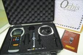
Fig. 3: Thermal resistivity measurement equipment detail.
Regarding the trench backfill material, the degree of compaction (based on the Proctor test) and the moisture content must be similar to those employed during the actual construction backfill operations. These tests are typically deferred to the construction phase, once the specific material intended for trench backfilling has been finalized.
2.6 Seismic Hazard and Site Characterization
For projects located in seismically active areas, it is essential to determine—in accordance with the seismic regulations of each country—the design parameters corresponding to the site-specific ground conditions, as well as the potential implications for the proposed structures.
The Vs30 parameter, defined as the time-averaged shear-wave velocity from the surface to a depth of 30 meters, is an internationally accepted parameter for site classification under the IBC (International Building Code), for the application of seismic design coefficients (Eurocode), and for liquefaction potential analysis.
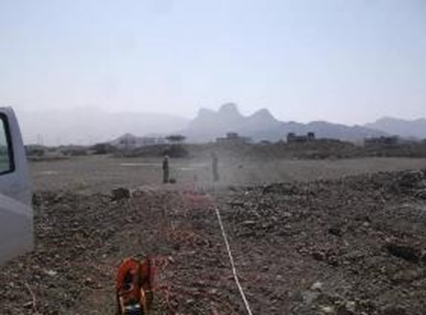
Fig. 4: Passive seismic profile.
The Passive Seismic or ReMi (Refraction Microtremor) method allows for the rapid and reliable determination of site Vs30 values. Furthermore, it enables the derivation of the geological model and the stiffness distribution with depth, providing the necessary data to characterize the ground response to seismic or cyclic loading.
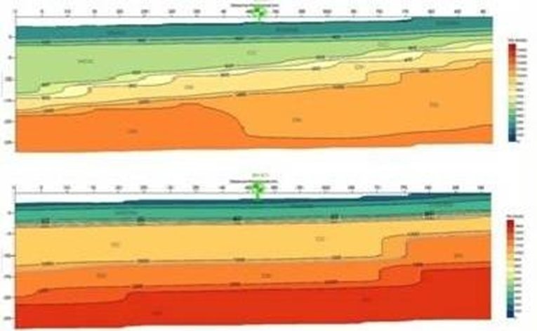
Fig. 5: Stiffness and Vs30
In certain countries, it is mandatory to determine the fundamental frequency and natural period of ground vibrations, for which the HVSR (Horizontal-to-Vertical Spectral Ratio) test is commonly employed.
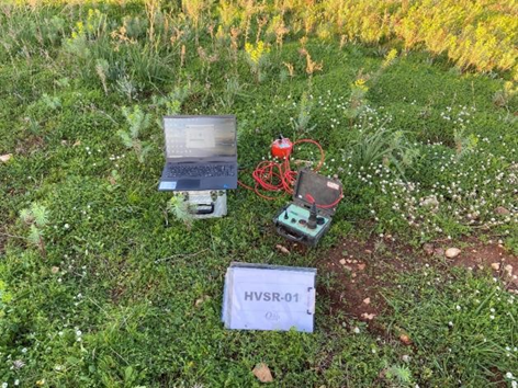
Fig. 6: HVSR test.
2.7 Ground Deformability
When determining the subgrade or sub-base category for road construction, or assessing the vertical deformability of shallow foundations in detail, tools such as the German dynamic plate load test (LWD - Light Weight Deflectometer) or the in-situ CBR test are employed. Both methods allow for multiple tests to be conducted quickly and efficiently within a single day, particularly in unsaturated soils.

Fig. 7: Zorn dynamic plate load test detail and graphical result.
If the near-surface soil is saturated, static plate load tests must be performed, although they are significantly more time-consuming than dynamic plate tests. They also require a reaction system, such as a truck loaded with sand
In the case of saturated clayey soils and high surface loads—a scenario less common in photovoltaic projects—it is necessary to conduct oedometer tests on undisturbed samples to evaluate long-term consolidation settlement.
2.8 Road Tests / Roadway Testing
The main access roads within the photovoltaic plant will experience very low Average Daily Traffic (ADT) volume; however, they require appropriate design to ensure durability, particularly when traversing soft or expansive soils that may necessitate subgrade remediation, isolation, or reinforcement prior to road construction. The nature and deformability of the natural subgrade must be characterized during the geotechnical investigation if the road alignment is known. To this end, in-situ CBR tests, dynamic penetrometer tests, and static or dynamic plate load tests may be employed. The bearing capacity of the materials to be used in the various road layers is typically addressed in a pre-construction phase, once the specific materials have been selected.
2.9 Expansive Clays and Collapsible Soils
It is common to encounter clays prone to shrinkage and cracking during the dry season, and swelling during the wet season. This poses a particular challenge in arid and semi-arid regions. Once potentially expansive clays are identified—for instance, through their high plasticity index—their swelling potential and cracking susceptibility must be quantified. This should be carried out through free-swell or, alternatively, swelling pressure tests at varying moisture contents, as well as linear shrinkage tests. Depending on the intensity of the swelling potential, preventive measures must be designed to minimize risks to the foundations.
If time permits, it is highly recommended to measure the thickness of the active zone by evaluating moisture content variations at different depths over a full annual cycle. Otherwise, it must be estimated based on bibliographic data and local climatological records. Swelling will be most pronounced near the surface and practically negligible at the base of the active zone. Only a portion of this active zone will undergo shrinkage cracking, with the crack depth becoming visible during the dry season. Measuring crack depth on excavation walls is strongly advised.
Collapsible soils are typically fine-grained, non-plastic soils, with or without the presence of sulfates, which may undergo collapse under changes in stress or moisture content. When such soils are encountered, specific testing—such as the collapse test in an oedometer cell—is required.
2.10 Soil Corrosivity
The potential for corrosion induced by chemical and electrochemical reactions between soil and buried metals—typically steel and galvanized steel—is of paramount importance in photovoltaic plants, where driven pile foundations are extensively used.
The assessment of corrosive potential is conducted in accordance with DIN 50929-3:2023, which we consider the most comprehensive standard, as it evaluates various soil parameters and electrical resistivity. Alternatively, local regulations are applied where applicable.
The standard assesses the corrosion resistance of hot-dip galvanized steel coatings. It does not quantify the specific thickness of the galvanization required for the project, which must be determined by a specialist or the galvanizing companies, rather than within a geotechnical study.
It is clearly outside the scope of a geotechnical study to address corrosion caused by atmospheric agents on the portion of the steel profile located above ground level.
3. DESIGN GUIDELINES. RECOMMENDED MEASUREMENTS
The following table provides the minimum field investigations required based on the plot area. The number of investigations should be increased or reduced depending on site-specific challenges (such as site geometry, topography, local geology, accessibility, existing installations, etc.). All investigations must be continuously supervised by a qualified professional (e.g., a geologist or similar) who is fully conversant with the project requirements and specifications.
Table 1. Recommended number of investigations according to plant size
| SURFACE (Ha) | TEST PITS | PENETRATION TEST | ELECTRICAL RESISTIVITY | THERMAL RESISTIVITY |
| <2 | 3 –5 | 3 –5 | 1-2 | 1 – 2 |
| 2 – 5 | 5 – 7 | 5 – 7 | 2-3 | 2 – 3 |
| 5 – 10 | 7 – 12 | 7 – 12 | 3 – 5 | 3 – 5 |
| 10 – 30 | 12 – 22 | 12 – 22 | 5- 9 | 5 – 9 |
| 30 – 100 | 22 – 40 | 22 – 40 | 9 – 11 | 9 – 11 |
| 100 – 300 | 40 – 60 | 40 – 60 | 11 – 15 | 11 -15 |
| >300 | 1 per 5 hectares | 1 per 5 hectares | 1 per 20 hectares | 1 per 20 hectares |
The investigations proposed by ORBIS TERRARUM serve as a baseline, which the geotechnical firm may complement with additional testing, such as core drilling, infiltration/permeability tests, dynamic plate load tests, or seismic refraction/passive seismic surveys in the event of sites with seismic risk.
Regarding corrosion, these projects may be supplemented with specific soil corrosion modeling tests.
4. LABORATORY TESTING
Laboratory tests can be divided into several categories. The first group corresponds to classification and state tests, which allow us to determine the soil type. The second group includes mechanical tests to assess the strength and deformability of the materials—whether soil or rock—as well as aspects such as potential expansivity and collapse risk. A third group refers to material reuse tests, where this item is necessary for the project. Finally, the fourth group comprises chemical tests to evaluate the aggressiveness of the soil and water toward concrete and steel (corrosion). The request for testing must always be made by the technician responsible for the study, based on the nature of the materials encountered (soil, rock, cohesive, non-cohesive, etc.).
As a guideline, the following table establishes a standard testing schedule to be conducted:
Table 2. Number of tests recommended for every 5 samples
| TEST | PER 5 SAMPLES |
| IDENTIFICATION AND STATE | |
| Sieve analysis | 5 |
| TEST | PER 5 SAMPLES |
| Límites de Atterberg | 5 |
| Determination of natural moisture content. | 5 |
| Dry and bulk density. | 3 |
| RESISTANCE | |
| Direct shear test. | 0,50 |
| Exploitation THE MATERIALS | |
| Maximum Dry Density (Modified Proctor). | 0,25 |
| CBR | 0,25 |
| Expansiveness and collapse | |
| Free swell of a soil. | 0,20 |
| Collapse index | 0,20 |
| Maximum swelling pressure. | 0,20 |
| Shrinkage index. | 0,20 |
| Rock testing | |
| Rock density | 0,75 |
| Inglés: Point Load Test (PLT) | 0,75 |
| Chemicals | |
| Water-soluble and acid-soluble sulfate content. | 1 |
| Baumann-Gully acidity | 1 |
| Organic matter content. | 1 |
| Soil pH | 1 |
| Determination of alkalinity/acidity. | 1 |
| Determination of chloride content. | 1 |
| Determination of sulfide content. | 1 |
| Aggressiveness of water to concrete. | 1 |
In addition to the tests described above, laboratory tests can also be performed to determine the previously mentioned electrical and thermal properties of the soils.
5. REPORTS
Geological-geotechnical reports are directly related to the scope of the geotechnical campaign and can be divided into:
- Report on works performed (or Factual report)
- Feasibility or preliminary report
- Final or design report
The different types of reports are described below.
Report on works performed (or Factual report)This report is a summary of the field investigations. No conclusions or recommendations are provided.
This report includes the minimum necessary data to define the site geology, geological hazards, pile driving feasibility, optimal areas, and basic recommendations to allow for preliminary design and cost estimation. In this case, the number of investigations and laboratory tests is lower than in a final study, as the scope is limited to providing general recommendations to the client for the preparation of a basic or preliminary project. The results of this report are not used for plant design. It is recommended that this report list the additional geotechnical investigations required to complete the data in the future for the design-stage geotechnical study.
Final or design reportThis report includes all relevant information and analyses performed based on the results of the geotechnical campaign and laboratory tests. The results of this report are used for the plant design. This report contains, at a minimum:
- Basic information: description of the project's main characteristics.
- Works performed: description of the bibliographic information consulted, all field works carried out, and a summary of the laboratory test results.
- Geology: regional and local geology, hydrogeology, geomorphology, etc.
- Seismic analysis: seismic site characterization based on national or international codes.
- Geological and natural hazards: description of the main hazards and an estimation of their risk level.
- Geotechnical characterization: description of the identified geotechnical units with a summary of their recommended geotechnical parameters.
- Aggressiveness to concrete and steel (corrosion).
- Thermal resistivity: thermal properties of the various geotechnical units.
- Excavability and slope design: Excavability recommendations for the different geotechnical units and recommendations for permanent or temporary slopes.
- Material reuse: Reuse of geotechnical units that can be excavated during plant construction.
- PV module foundation design: foundation type and zoning will be defined
- In the event that steel pile driving is not viable as a primary option, alternative methods will be explored, such as pre-drilling, the use of ground screws, or shallow foundations. For rocky terrain, micropiles or shallow foundations shall be used.
- Shallow foundation design: Foundation type and design calculations for inverter stations and lightweight structures.
- Providing electrical resistivity data for the design of the grounding network.
It is professional best practice to conduct the geotechnical site investigation first, followed by a separate study on foundation resistance and deformation, utilizing full-scale field tests once the cross-section and moment of inertia of the metal profiles, as well as the design loads, are finalized. These investigations are known as pile-driving (driveability) tests and static load tests (pull-out/compressive/lateral tests). ramming and pull out tests por su denominación en inglés. El análisis pormenorizado de los resultados permitirá definir la longitud óptima de hincado y validar las deformaciones obtenidas.
Layouts & Profiles
It is essential that the report provides representative geological columns for each of the identified zones.
Furthermore, it is essential to provide a detailed surface geological map and a pile-driving feasibility plan. This plan should enable the design of the pile-driving and pull-out test campaign, based on the expected soil conditions—though it may be subject to revision following the results of the pull-out tests.
Appendices
All field investigations will be included in the corresponding appendices of the Geotechnical Report, providing a detailed description for each activity, including: georeferenced coordinates, equipment utilized, dates, geological-geotechnical descriptions by specialized technicians, samples collected, and other relevant observations. Additionally, a comprehensive photographic record of both the activities performed and the general site conditions will be provided.
Deadlines
The typical lead times for these studies—which may vary based on project size—are as follows: one to two weeks for field reconnaissance, depending on the project’s scale; two weeks for laboratory testing and geophysical data interpretation (specifically Electrical Resistivity Tomography); and an additional one to two weeks for the drafting of the final geological-geotechnical report.

